2. THE NATURE OF TEMPERATURE ERRORS
The relation between the unknown value of the non-electrical quantity, which we shall denote by X, and the value of the electrical output signal of the sensor, which we shall denote by U, is called the transfer characteristic and is described by the function f.1
Owing to the presence of signals interfering with the operation of the sensor, such as a change in ambient temperature, supply-voltage fluctuations, the presence of vibration, changes in atmospheric pressure, the presence of interfering electromagnetic fields, etc., f is a function of many variables. In the further considerations we shall confine ourselves to taking into account only the effect of changes in the ambient temperature T, and so we shall assume that f is a function of the two variables X, T.
The output signal u of the sensor may take the form of a change of voltage, current, resistance, capacitance, mutual inductance, etc.
For the unification of the receiving instrumentation in an automatic control system, the signals being processed should be standardized. To this end a measuring transducer consists of a sensor and a supplementary electronic signal-conditioning circuit, which brings the output signal of the transducer to the accepted standard signals1. Such circuits, besides standardizing the transfer characteristic of the sensor, often make possible a linearity correction of the transfer of the non-electrical quantity X and compensation of the effect of ambient temperature. Thus the output signal U of the transducer is defined
¹ The signals most commonly encountered at present in industrial automation are the current signals 0 to 6 mA, 4 to 20 mA and the voltage signals 1 to 5 V. For a given controlled plant, one signal range is usually used, e.g. 4 to 20 mA.2
by the transfer characteristic described by the function g:
Temperature compensation can be realized in two ways [2]:
- the compensation circuit makes possible the correction of the temperature error of the sensor only, while the temperature error of the signal-conditioning circuit should be negligibly small in comparison with the error of the sensor. In such a case the use of expensive components and circuit designs in the signal-conditioning circuit is required,
- the total temperature error of the transducer is compensated, this being the superposition of the error of the sensor and of the signal-conditioning circuit, both at the same temperature, which permits the use of cheaper electronic components and simpler circuit designs. This case can be reduced to the first case on the assumption that the error of the signal-conditioning circuit is referred to the sensor, and that in the error analysis an equivalent sensor error will be considered, consisting of two components: the error of the sensor itself and the equivalent error of the signal-conditioning circuit.
As already mentioned, the transfer characteristic is defined by a function of two variables: the value of the output signal of the transducer and the value of the measured non-electrical quantity, and so its graphical representation will be a surface described by relation (2) (Fig. 1a). For practical reasons, several parameters characterizing the values of the temperature error of the transducer have been adopted. The most commonly used are: (a) the temperature error (drift) of the lower range value (the so-called "zero"), defining the effect of changes in ambient temperature on the value of the output signal U at a constant value of the measurand X equal to the lower value of the measuring range; the graphical interpretation of this error is the line of intersection of the plane defined by relation (2) with the plane (Fig. 1b)
(b) the temperature error (drift) of the upper value of the measuring range (the so-called "span"), defining the effect of changes in ambient temperature on the value of the measurand equal to the upper value of the measuring range; the graphical interpretation of this error will be the line of intersection of the plane defined by relation (2) with the plane (Fig. 1c).
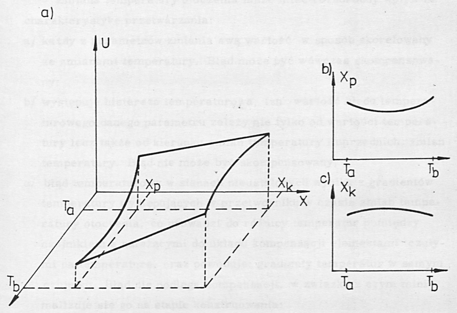
(c) the temperature error (drift) of the span, defining the effect of changes in ambient temperature on the output signal increment caused by a change of the value of the measurand from the lower value to the upper value ; this parameter is given in data sheets as an alternative to the temperature error of the upper range value.
A change in ambient temperature may have various effects on the transfer characteristic: (a) each of the parameters changes its value in a manner correlated with the changes of temperature. The error can then be compensated; (b) temperature hysteresis occurs, i.e. the value of the temperature error of a given parameter depends not only on the value of the temperature but also on the direction of temperature changes and on previous temperature changes. The error cannot be compensated; (c) the temperature error in transient states results from temperature gradients occurring in the transducer during changes in ambient temperature, which leads to a temperature difference between the sensor and the temperature-sensitive elements belonging to the compensation circuit, and causes temperature gradients in the sensor itself. The error is not subject to compensation, and is therefore minimized at the design stage; (d) the temperature-decay error (Engl. "temperature decay"), that is, an error occurring immediately after a change of temperature and decaying gradually to zero. It is not connected with transient states, but with changes, for example, in the crystal lattice of the sensor material, and it is the greater, the greater the change of temperature and the longer the time spent at the temperature preceding the change. The decay time of this error may be very long, of the order of several tens of hours. The error is not subject to compensation; (e) temperature non-repeatability, in which the value of a given parameter may undergo a permanent change as a result of temperature changes,
especially in the case of prolonged operation near the temperature extremes. In such a case the transducer must be calibrated to recover the original value of the parameter. The error is not subject to compensation.4
Thus only the temperature error named in item (a) can be subject to compensation. The remaining components of the error can only be reduced by selecting a suitable technology and design of the sensor and transducer.
The purpose of compensation is to reduce the equivalent sensor error. The permissible value of the temperature error (the error limit) can be defined in two ways.
In the first way, the maximum value of the temperature error is specified, reckoned relative to the value of the given parameter at the reference temperature , independently of temperature (Fig. 2a). Such requirements may be imposed where the mean-square error is to be limited for random values of the ambient temperature, as occurs, for example, when transducers are used in material-balance systems for the final product of an industrial plant.
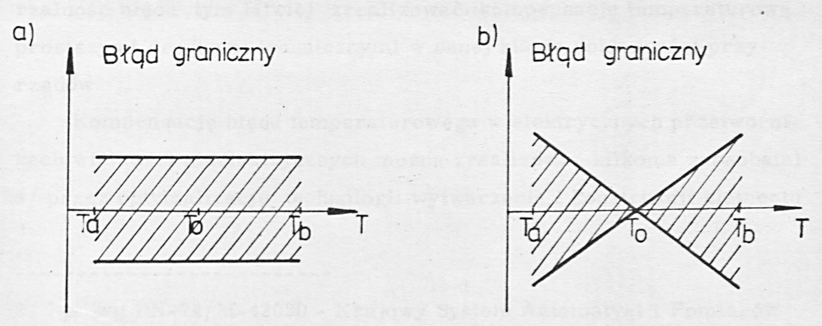
Labels: Błąd graniczny = error limit
In the second method2, the value of the slope of the error limit as a function of temperature is limited. Taking a certain temperature as the temperature relative to which we measure the temperature error, the region of permissible values of temperature errors lies between two straight lines intersecting at the temperature , with a slope equal to the imposed error limit (Fig. 2b).
The value of the temperature error limit is related to the accuracy class of the transducer. According to the Polish Standard3, the value of any additional error, including the temperature error, should not exceed the value preceding (in the series of accuracy classes) the value adopted as the accuracy class of the device. The temperature error of the transfer characteristic should be measured every 10 °C at an input signal of the non-electrical quantity equal to 0 %, 20 %, 40 %, 60 %, 100 % of the span for which the transducer has been calibrated.5
Considering the value of the temperature error of a given parameter over a population of transducers of a certain size, e.g. equal to the annual production of an industrial plant, one can distinguish a systematic (repeatable) part of the error and a random part, the ratio between these parts varying from zero (no repeatable part of the error) to a value close to 100 %. The greater the repeatability of the error, the easier it is to realize temperature compensation by simpler technical means within a given accuracy class of instruments.
Compensation of the temperature error in electrical transducers for non-electrical quantities can be realized in several ways: (a) by optimizing the manufacturing technology and the design of the transducing
² E.g. according to Polish Standard PN-74/M-42020, National System of Automation and Measurement POLMATIK — General requirements and tests — Additional errors are to be specified per 10 °C of change in the temperature of the ambient and of the measured medium. ³ Polish Standard PN-73/M-42024, Industrial automation — Analogue electrical elements and devices — Requirements and tests.
element [3–24], e.g. a strain gauge. With this method one most often stops at the compensation of one parameter (zero) of the transfer characteristic of transducers made using highly repeatable transducing elements and with not very demanding requirements as to the compensation accuracy. It usually requires the use of several transducing elements in the sensor for the non-electrical quantity, enabling the use of a special electronic circuit, e.g. a bridge; (b) by means of a special non-electrical construction producing an additional, temperature-dependent value of the non-electrical quantity being converted [25–31]. Owing to great difficulties of execution and low compensation accuracy, this method is now of historical significance only; (c) by placing the compensation circuitry in the analog part of the electronic circuit conditioning the sensor signal. This way is at present the most widespread [1, 32–76], owing to:
- the worldwide tendency in automation towards the integration of the sensor with the electronic signal-conditioning circuit,
- the possibility of obtaining small temperature errors of the compensated transducers,
- the possibility of unambiguous compensation of the temperature errors of the electronic signal-conditioning circuit,
- the possibility of compensating transducers whose sensors have a temperature error that is not repeatable from one unit to another,
- the decided predominance, at the present time, of analog automatic control systems over digital control systems; The method is often used together with the compensation named in item (a), and more rarely with the simultaneous use of the compensation named in item (b); (d) by realizing the compensation in the digital part of the automation system [78, 79], by software or by hardware. At the present time such a
method is expensive, but nevertheless it allows the best measurement performance to be obtained. In the author's opinion, this method will supersede all other compensation methods in automation transducers once there is a decisive fall in the prices of microprocessors and a reduction in the supply current they draw, together with an increase in their level of integration and the introduction of cheap, easily programmable read-only memories (ROM) in which an individual correction program would be stored; (e) by thermostatic control of the sensor. Such a method eliminates the need for temperature compensation. It is, however, used only in very accurate laboratory instrumentation, e.g. [80].
From the above classification of the methods in use it follows that in an accurate measuring transducer produced in series, whose price is not a matter of indifference, the only design for temperature compensation at present is variant "c" — the use of a compensation circuit in the analog part of the electronic normalizing circuit, possibly with the use of variant "a" or "b".
The known compensation designs [1, 32, 77] are characterized by a mutual dependence either of the settings of the compensation circuit for one parameter (e.g. zero) on the settings of the compensation circuit for the second parameter (e.g. span), or of the settings of the compensation circuit at different temperatures. As a result the compensation procedure is tedious, and carrying it out requires highly qualified personnel and, not infrequently, recourse to a computer program.
Very high requirements as to metrological parameters (stability, temperature coefficient) are usually imposed on the elements correcting the temperature error. The values of these elements are determined only after the completion of the compensation procedure, that is, in the last phase of production. Allowing for the individual spread of temperature errors in each unit of the transducer requires keeping a suitably large stock of components in store (e.g. for the Honeywell Class 41 transducers [33, 39, 40],
10 components in the compensation circuit are changed, with values selected from a set of about 130 values) or making them in-house [33].6
Translator's notes
- original reads "którą oznaczymy przez U" for the sensor output, although equation (1) and the following paragraph use u for the sensor output and U for the transducer output; kept as printed. ↩
- original reads "0...6 mA"; elsewhere in the thesis the standard current signal is 0 to 5 mA. Kept as printed. ↩
- in items (a) and (b) the original says "płaszczyzny określonej zależnością (2)" (the plane defined by relation (2)), although the same paragraph has just called the graph of (2) a surface ("powierzchnia"); translated literally as "plane". ↩
- original reads "błąd zanikowy /ang. temperature decay/"; the author's own English term is kept. In item (e) the original ends page 12 with a comma and resumes page 13 with a stray full stop before "zwłaszcza" (especially); read as one sentence. ↩
- "additional error" (błąd dodatkowy) is the Polish-standard term for the error due to an influence quantity such as temperature; IEC usage would be "variation". The percentage series is printed as "0%, 20%, 40%, 60%, 100%" — 80 % is absent; kept as printed. ↩
- original reads "dopiero do zakończeniu procedury kompensacji" (page 16); "do" (until) is a typist's slip for "po" (after), translated as "after". ↩